

Original Articles
Algorithm of Myoelectric Signals Processing for the Control of Prosthetic Robotic Hands
Algorithm of Myoelectric Signals Processing for the Control of Prosthetic Robotic Hands
Journal of Computer Science and Technology, vol. 18, no. 1, 2018
Universidad Nacional de La Plata
Received: 08 February 2018
Revised: 21 March 2018
Accepted: 09 April 2018
Abstract: The development of robotic hand prosthetic aims to give back people with disabilities, the ability to recover the functionality needed to manipulate the objects of their daily environment. The electrical signals sent by the brain through the nervous system are associated with the type of movement that the limbs must execute. Myoelectric sensors are non-intrusive devices that allow the capture of electrical signals from the peripheral nervous system. The relationship between the signals originated in the brain tending to generate an action and the myoelectric ones as a result of them, are weakly correlated. For this reason, it is necessary to study their interaction in order to develop the algorithms that allow recognizing orders and transform them into commands that activate the corresponding movements of the prosthesis. The present work shows the development of a prosthesis based on the design of an artificial hand Open Bionics to produce the movements, the MyoWare Muscle sensor for the capture of myoelectric signals (EMG) and the algorithm that allows to identify orders associated with three types of movement. Arduino Nano module performs the acquisition and control processes to meet the size and consumption requirements of this application.
Keywords: EMG, Prosthesis, Robotic, Arduino, Hand, Bionic.
1. Introduction
Hand prostheses controlled by bioelectrical means, constitute the type of artificial limb with the highest degree of rehabilitation, since they can synthesize the aesthetic aspect, the strength and speed of grasping, as well as many possibilities of adaptation to different degrees of disability. Myoelectric control is the most widespread control scheme due to its non-invasive features. It is based on a physiological principle that indicates that whenever a muscle in the body contracts or flexes, there is a small electrical signal (bioelectric) that produces it. This comes from a chemical interaction in the body and produces a very small signal (5 to 20 μV) that can be captured with surface electrodes (called patches or pads) mounted in contact with the skin.
Since there is a correspondence between muscle activity and electromyoelectric signals (EMG), information can be extracted from them to identify movements. This classification process has been studied in depth [1], and for this a wide variety of algorithms is available, whose efficiency will be evaluated.
The use of myoelectric signals for the control of prostheses has evolved from simple ON-OFF implementations to more advanced since the incorporation of microcontrollers for the acquisition, processing and control of them that also offer additional benefits such as size, consumption and cost [2] [3] [4].
There is a lot of valuable information regarding the procedures for the identification and classification of movements applied to the development of prostheses [5] [6].
The current work on the topic includes the analysis of different features using multiple sensors, addressing the possibility of using a classification algorithm for movement detection [7] [8] [9]. Despite this information being valuable, it conflicts with the idea of using a single sensor to favor portability, since this would end up classifying a single movement. Due to portability, it is expected to obtain as much information as possible using a minimal number of muscles but retaining an useful number of movements to be classified in real time.
The sensor used to measure the EMG signal is the MyoWare Muscle Sensor and an Arduino Nano board to perform the sampling of the signal.
In particular, it is desired to detect three movements of the hand from a sensor in the radial flexor muscle of the carpus in the forearm. The three movements are shown in Fig. 1 and consist of fist closure (called c), pressure with the fingertip (p) and flexion of the wrist inward (f).
The signal obtained is sent to a portable PC where it is conditioned, segmented and filtered in order to extract useful features. These features are the mean value of the signal in absolute value (MAV), waveform length (WL), zero crossings (ZC) and sign change in the slope (SSC).


For different movements, the average values of some features have differences so it is considered that it is possible to divide the space in such a way that a classification can be made. Three classification algorithms were tested: Support Vector Machines, Nearest Neighbors and Neural Networks, using the Machine Learning for Python libraries, scikit-learn [10]. The ways to implement the classification consist of two procedures: one in batches and another in line. For the first case, samples of the different movements are obtained and training and test sets are designated. For the second one, which is the case of utility and interest, samples are taken simultaneously with the processing. After taking the first samples, which train the classifier, the next samples are classified simultaneously with the capture of the movement.
2. Prosthesis Components
2.1. Open Bionics Robotic Hand
Open Bionics is a company dedicated to the diffusion and commercialization of bionic hands built using scanning technologies and 3D printers. These prostheses are based on the structure and functionality of the human hand, since it is the most versatile and skillful end effector known. The design uses an anthropomorphic model both in its kinematics and in its transmission and drive system. The steps in the construction start with the scan that allows replicating the patient's amputated organ, to create a three-dimensional model of its geometry. This procedure allows to build prostheses that fit properly. Myoelectric sensors placed on a healthy muscle in the patient's limb are used to capture the electrical signals to generate the different grip patterns in the fingers.
2.2. MyoWare Myoelectric Sensor
This sensor of myoelectric signals measures, filters, rectifies and amplifies the electrical activity of the muscle and produces at the output, an analog signal with sufficient amplitude to be read and processed by a microcontroller that controls the movements of the artificial hand. This kind of sensors is traditionally used for the investigation and diagnosis of neuromuscular disorders. In this work, it is combined with an Arduino Nano microcontroller module that offers the most appropriate size, consumption and computing power characteristics for this application.
2.3. Acquisition Module
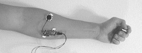
An Arduino Nano board is used to take samples of the signal delivered by the MyoWare sensor at 1ks / s. The sensor is connected to the carpal radial flexor muscle as indicated in Fig. 2 and the reference electrode outside the zone of muscle myoelectric activity under analysis.
The test sets that were taken consist of 100 repeated movements every 3 seconds of each one, called c, f and p. Samples were serially sent to a portable PC running an acquisition program in Python and later they are used for the characterization of each of the three movements.
3. Processing
The data sets obtained correspond to the EMG signal, are centered on a voltage level, have variations in their average value and are not stationary. Before the extraction of features that allow classification, the signal is filtered and segmented.
Filtering: an Butterworth 10th order IIR passband digital filter is used using SciPy [11] with cutoff frequencies of 50 and 400 Hz based on empirical results and studies [12].
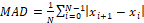
Segmentation: the signal segments that are not null are extracted, that is, where the muscle is active. For this, the operation Eq (1) is performed, which consists of differentiating the signal and obtaining its average value by taking windows of length N samples. Then a threshold is applied to detect the peaks of this new signal and the EMG is segmented with the peaks as its center.
 [Eq.1]

3.1. Feature extraction
From the processed signals, four features of the temporal domain were extracted that were able to differentiate the three movements of interest. The selection was decided based on its simplicity, although other works extend the analysis to a much larger number [7] [8] [9]. These features are calculated over a time window of the signal. After the segmentation is done, a fixed number of samples is taken to evaluate each characteristic. The corresponding operations are the following:
1. Mean Absolute Value (MAV): the average value of the values of the window is calculated in absolute value Eq (2).
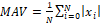 [Eq. 2]
2. Waveform Length (WL): provides information on the complexity of the waveform length, being a measure of both its amplitude, frequency and duration in a single parameter [1]. It is calculated as the sum in absolute value of the differences between two successive samples Eq (3).
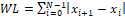 [Eq.3]
3. Zero Crossing (ZC): count the number of crosses by zero in the segment. In order to avoid zero crossing due to noise, a threshold is added from which the crossing is recorded Eq (4).
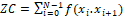 [Eq.4]
 [Eq.5]
4. Slope Sign Change (SSC): similar to the ZC feature but applied on the slope of the waveform Eq (6).
 [Eq.6]
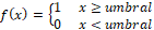
To ensure repeatability, the features are normalized with respect to their mean and standard deviation. In Fig. 4, it is shown how this normalization influences the separation of the categories, when applying PCA (Principal Component Analysis).
The improvements after normalization are remarkable and their reference coordinates are calculated during training and stored to define the clusters that allow, later, to identify the movement associated with the myoelectric signal.
3.2. Classification
Once the features for different repetitions of the different movements have been obtained, a classifier is searched that, for a minimum number of training samples, it can classify with a tolerable error the new samples.
Three classification algorithms were chosen to compare results later:
Support Vector Machines: it consists of a non-linear mapping of the entrance to a larger space. Then a hyperplane is found that generalizes the separation of the space of features [13] [14].
K-Nearest Neighbors: labels are assigned to the entries based on their k neighbors. A volume with the new entry in its center is evaluated as a class according to the points that are enclosed in that volume [9] [15].
Neural Networks: also called multilayer perceptron, consists of a set of inputs that are transformed into outputs according to the coefficients of the hidden layer (s). In particular, it trains with the inputs and outputs, and the coefficients are obtained using a backpropagation algorithm based on a descendant gradient scheme [16].
To evaluate the performance of the classifiers, training samples are initially generated and then a new set of samples to validate the classification. This emulates the intended behavior of the proposed application.
4. Results
In order to evaluate the results of the system, two phases were implemented: the first one consists of generating a large dataset of movements involving 100 of each one of them; the second one consists of evaluating online data from different users. The purpose of the first implementation is to test different classifier parameters and obtain preliminary results. Also different sizes of training sets (10, 20 and 30), for each movement, are proposed in order to find one which produces a better fit with current data using the less number of training samples as possible. The second phase is used as a real test of how the system behaves with different users.
4.1. Preliminary results
Training sets of 30 samples per movement were generated, defying the different parameters associated with each classifier. Each training set is tested against a dataset containing 100 moves per class prepared beforehand. With this procedure it is expected to find a training set that manages to classify, with the highest success rate, each type of movement. The algorithms used were those implemented by the Python library scikit-learn [10]:
Lineal Kernel
Kernel RBF (gaussian)
Uniform Weight
Weights inversely proportional to the distance
10 neurons in hidden layer
50 neurons in hidden layer
100 neurons in hidden layer
Each classifier is trained with 10, 20 and 30 samples per movement, to determine for each number of samples which has the best performance. To evaluate this procedure, a score between 0 and 1 is used, which is calculated as shown in the Eq. (7)
Score = successful trials/ total trials (Eq.7)
| Sorter 10 | 20 | 30 | ||
| SVM | ||||
| Linear Kernel | 0.822 | 0.844 | 0.800 | |
| RBF Kernel | 0.578 | 0.644 | 0.811 | |
| K-NN | ||||
| Uniform | 0.411 | 0.600 | 0.811 | |
| Distance | 0.622 | 0.667 | 0.867 | |
| Neural Network | ||||
| 10 | 0.856 | 0.844 | 0.867 | |
| 50 | 0.822 | 0.811 | 0.889 | |
| 100 | 0.878 | 0.878 | 0.878 | |
In order to implement the system, the most consistent classifiers were used for different number of training samples, especially those that have the best performance for a reduced number of samples. This procedure seeks to find the minimum number of training samples that generate a classification as accurate as possible. This is because after a certain time, the user becomes fatigued and loses concentration producing incorrect results. In addition, training protocols were established that allow the testing of different users to be standardized.
4.2. Online Results
To evaluate the results, a program was developed that generates different training and classification in real time. The classifiers with the best performance (neural network and SVM) with different number of samples were used and 30 movements were classified sequentially to determine which combination is most appropriate. The results of each case are presented in Table 2, 3.
| 10 | 20 | 30 | |
| Closure | 0.9 | 0.8333 | 0.8 |
| Flexion | 0.9667 | 0.9667 | 1 |
| Pressure | 1 | 0.8667 | 1 |
| Average Score | 0.9556 | 0.8889 | 0.9333 |
| 10 | 20 | 30 | |
| Closure | 0.6667 | 0.8333 | 0.9333 |
| Flexion | 0.9 | 0.8667 | 0.7667 |
| Pressure | 1 | 0.9333 | 0.9667 |
| Average Score | 0.8556 | 0.8778 | 0.8889 |
Table 2 shows that the best scores were obtained for the SVM classifier. It was chosen to take 10 samples because the results indicate that it is an adequate number, considering also that the user can maintain the concentration during the procedure. The greater the number of repetitions, the faster it becomes tired and distracted, which can introduce variations in myoelectric signals generated and recorded.
To validate these procedures and verify the repeatability of the parameters used in other people, this training was repeated with 6 different users. The employed methodology consisted of placing the sensor in the arm of the different users recording the results and calculating the scoring of the classification for each requested movement.
The average performance of the tests is shown in Table 4 where the efficiency of the classifications studied is observed.
| SVM | Neural Network | |
| Closure | 0.9 | 0.7333 |
| Flexion | 0.9 | 0.6 |
| Pressure | 0.8667 | 1 |
| Average Score | 0.8889 | 0.7778 |
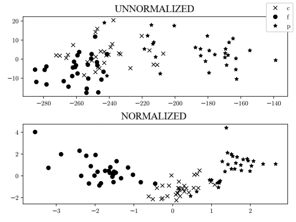
5. Applications
The results obtained were tested to control an experimental hand as shown in Fig. 5, where it is seen the fingers and the servos that move them. Commands were programmed that are sent by serial port to an Arduino Nano board that controls the operation of the servos and that correspond to the classified movements, as it is seen in [17].
The schematic of Fig. 6 shows the complete circuit of the hand, with the myoelectric sensor connected to the analog channel 0 of the Arduino board, the PWM outputs to the five servos that act on the fingers of the hand and the USB connection to the notebook for testing the algorithms.

The functions of the Arduino library that allow to operate the servos for the movement of the fingers are included in servo.h and the instructions to configure them are presented in the Algorithm 1.
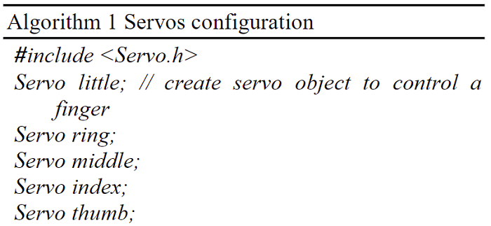
The functions used to produce the movements of the fingers are those that allow to program the PWM outputs with the required angle, the instruction little.write(150) is an example of code for the little finger and an angle of 150º:
The range of movement of a servo covers from 0º to 180º, with these values the maximum displacement is obtained. In this work a range of 130º, between 20 and 150, is enough to move the fingers. Table 5 shows the values in degrees with which each of the servos is programmed to reproduce the positions c, p, f.
| little | ring | middle | index | thumb | |
| c | 20 | 20 | 20 | 20 | 150 |
| p | 150 | 150 | 150 | 20 | 150 |
| f | 15 | 150 | 150 | 150 | 20 |
6. Conclusions
Three classes of movements were classified using SVM and Neural Networks. The results of these tests showed that SVM is the most efficient without requiring large amounts of samples to train the classifier. This aspect is relevant because it consists of a procedure that does not take time to distract or tiring the user.
The developed classification was successful, showing approximately 90% success, considering that it employs a simple training and an economic and simple design, consisting of a sensor and a microcontroller module of low cost, size and consumption. The processing algorithm presents characteristics of complexity, size and speed that would allow its adaptation to the C language of the Arduino environment. In this way, in a Nano module, the acquisition, processing and control stages that give the prosthesis the autonomy characteristics of a portable device can be integrated. This is the objective of the next stage of the Project.
Finally, the aspects of this design proposal, initially oriented to a hand prosthesis, make it offer accessible and extensible solutions to address a broad spectrum of disabilities.
References
[1] B. Hudgins, P. Parker, and R. N. Scott, “A new strategy for multifunction myoelectric control”, IEEE Transactions on Biomedical Engineering, vol. 40, pp. 82–94, 1993.
[2] J. Brazeiro, S. Petraccia, M.Valdés. Mano controlada por señales musculares. BSc Thesis, Universidad de la República, 2015.
[3] R.G. Clement, K.E. Bugler , C.W. Oliver. “Bionic prosthetic hands: A review of present technology and future aspirations”. The Surgeon. vol. 9, pp. 336-340,2011.
[4] A.E. Schultz, T.A. Kuiken. “Neural interfaces for control of upper limb prostheses-the state of the art and future possibilities”. American Academy of Physical Medicine and Rehabilitation. vol.3, pp. 55-67,2011.
[5] M. Hakonena, H. Piitulainenb, A. Visala. “Current state of digital signal processing in myoelectric interfaces and related applications”. Biomedical Signal Processing and Control. vol. 18, pp. 334-359, 2015.
[6] M. A. Oskoei, H. Huosheng. “Myoelectric control systems a survey”. Biomedical Signal Processing and Control. Vol.2, pp. 275-294, 2011.
[7] A. Phinyomark, S. Hirunviriya, C. Limsakul, and P. Phukpattaranont, “Evaluation of emg feature extraction for hand movement recognition based on euclidean distance and standard deviation”, International Conference on Electrical Engineering /Electronics Computer Telecommunications and Information Technology (ECTI-CON), pp. 856–860, 2010.
[8] A. Phinyomark, P. Phukpattaranont, and C. Limsakul, “Feature reduction and selection for emg signal classification,” Expert Systems with Applications, vol. 39, no. 8, pp. 7420–7431, 2012.
[9] P. Azaripasand, A. Maleki, and A. Fallah, “Classification of adls using muscle activation waveform versus thirteen emg features”, 22nd Iranian Conference on Biomedical Engineering (ICBME), pp. 189– 193, 2015.
[10] F. Pedregosa, G. Varoquaux, A. Gramfort, V. Michel, B. Thirion, O. Grisel, M. Blondel, P. Prettenhofer, R. Weiss, V. Dubourg, J. Van- derplas, A. Passos, D. Cournapeau, M. Brucher, M. Perrot, and E. Duchesnay, “Scikit-learn: Machine learning in Python”, Journal of Machine Learning Research, vol. 12, pp. 2825–2830, 2011.
[11] E. Jones, T. Oliphant, P. Peterson, et al., “SciPy: Open source scientific tools for Python.” 2001. Available at:
[12] V. Zschorlich, “Digital filtering of emg-signals”, Electromyography and Clinical Neurophysiology , vol. 29, pp. 81–86, 1989.
[13] C. Cortes, V. Vapnik, “Support-vector networks”, Machine Learning, vol. 20, pp. 273–297, 1995.
[14] “Support vector machines.” Available at: http://scikit-learn.org/ stable/modules/svm.html. Accessed on 2017-10-17.
[15] “Nearest neighbors.” Available at: http://scikit-learn.org/ stable/modules/neighbors.html. Accessed on 2017-10-17.
[16] “Neural networks models (supervised).” Available at: http://scikit-learn.org/ stable/modules/neural_ networks_supervised.html. Accessed on 2017-10-17.
[17] “Prótesis Mano Robótica”. Available at: https://www.youtube.com/watch?v=-85fNRu4yp8&feature=youtu.be

