

Articles
Dose Rate Profile Inside the Spent Fuel Storage Pool in Case of Full Capacity Storage
Journal of Nuclear Physics, Material Sciences, Radiation and Applications
Chitkara University, India
ISSN: 2321-8649
ISSN-e: 2321-9289
Periodicity: Bianual
vol. 8, no. 1, 2020
Received: 28 January 2020
Revised: 19 April 2020
Accepted: 11 May 2020
Published: 10 August 2020

Abstract: The storage pool is connected to the main pool via transfer channel to facilitate transporting the spent fuel under water that avoiding radiation dose rising in the working area in the reactor. The storage pool was prepared to store 800 spent fuel elements that considering the maximum capacity of storage. The spent fuel elements in the storage pool have different decay times depending on the times of extraction from the core. Assuming conservatively, that the spent fuels of the 5-years decay time would be stored in the lower rack and the spent fuels, of decay time ranged between 10 days and 5 years, would be stored in the upper rack. The dose rate was profiled in the region above the upper rack using SCALE/MAVRIC code applying adjoint flux calculation as a variance reduction technique. The results show that the dose rate values in the region above the pool surface would be lower than the permissible limits.
Keywords: Radiation dose, Spent fuel, Storage pool.
1.Introduction
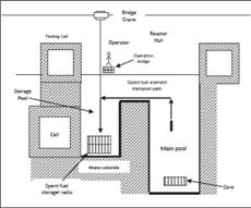
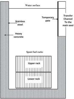
Spent fuel storage in open pool type reactor must be studied carefully from the radiological point of view since it is located in a working area where the operators would be always founded during the different tasks in the reactor. Figure 1 shows that the storage pool is connected with the main pool through transfer channel that enables transporting the spent fuel elements from the core to storage pool under water surface for verifying the least risk of radiation exposure. The storage pool was prepared as a temporary storage and designed to store around 800 spent fuel elements (SFEs) [1]. It was provided with two stainless steel rectangular racks; each one can store 400 spent fuel elements. The lower rack locates in the bottom of the pool and when it reaches the full capacity, the upper rack will be constructed above it to receive the following spent fuel elements as shown in Figure 2.
Studying the radiological dose rate profile inside the storage pool enables determining the radiation dose rate values especially in the upper region of the storage pool which locate adjacent to the working area of the reactor [2]. SCALE/MAVRIC code [3] was used to evaluate the dose rate distribution in the storage pool in case of the full capacity condition. In this model, It was verified that the neutron dose rate contribution from spontaneous fission and (alpha, n) reactions is negligible with respect to the photon dose rate.
2. Materials and Methods Feature of the Fuel Element
The core is built on a supporting grid having 6×5 positions available for placing fuel or irradiation boxes. The core consists of 29 fuel elements (FE) containing parallel fuel plates and irradiation box. Every fuel element has 19 aluminum fuel plates, each plate having a meat made by a dispersion of U3O8 particles with an enrichment of 19.7% in weight of 235U in a continuous matrix of pure aluminum [1]. The plate active zone is 80 cm×6.4 cm with a meat thickness of 0.7 mm and the aluminum cladding thickness of 0.4 mm.
The Spent Fuel Element Spectrum
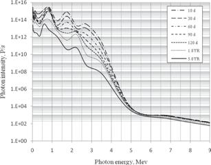
The fission products and actinides photon source was calculated using the isotope generation and depletion code, ORIGEN2.1 4[. In ORIGEN2.1 code, the cross sections for the fission product nuclides were obtained from ENDF/ B-IV and the cross sections for the actinides and structural material elements were obtained from ENDF/B-V. The source was calculated for a 235U mass of 404.7 g per fuel element. Assuming that each fuel element was irradiated continuously to a power of 0.759 MW considering a maximum discharge burn-up. The photon spectrum was determined using the ORIGEN2.1 18-groups photon energy structure at decay time ranging between 10 days and 5 years as shown in Figure 3.
Arrangement of SFEs in the Racks
The spent fuel elements are stored in the lower rack till reaching its full capacity, and then the upper rack will be constructed above the lower one to receive the following spent fuel elements. The lower rack needs more than 16 years for reaching the full capacity of storage assuming that two spent FEs are discharged from the core to the storage pool every month. For conservative calculation in this study; it was assumed that all the spent FEs in the lower rack having 5-years of decay time. The upper rack is filled with spent FEs of decay time ranging between 10 days to 5 years and for conservative calculations, it was assumed, as shown in Table 1, that:
| No of SFE in the upper rack Correspondance decay time 2 10d 2 30d 2 60d 2 90d 16 120d 96 1yr 280 5 yrs | |
• All the SFEs (96 SFEs), that having decay time ranged between 1 yr to 5 yr, are considered to have a corresponding decay time of 1 yr.
• The residuals (280 SFEs) are considered to have decay time of 5-yr.
2.4 The SCALE/MAVRIC Model
MAVRIC sequence in the SCALE code system was prepared to evaluate the radiation dose rate resulting from the shielding problem [5]. It was used to modeling the open pool storage that loaded with the maximum capacity of 800 spent fuel elements. Simplifying the calculations by assuming that the first rack was loaded with spent fuel elements of 5-years decay time and the upper rack was loaded with spent fuel elements of decay time ranged between 10 days to 5 years.
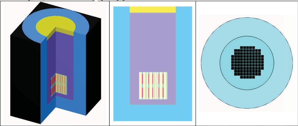
Figure 4 shows the spent fuel storage modeled using KENO3D. Denovo calculation was used with the parameters of qudrature of 8 and legendre of 3 [6]. The model used the 27N19G library from the SCALE code in the calculations. Adjoint flux calculation was used as a variance reduction technique to prepare the importance map and consequently evaluating the radiation dose mapping inside the storage pool [7]
3. Results and Discussion
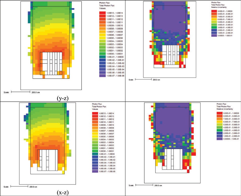
Figure 5 shows the photon flux distribution inside the storage pool around the spent fuel elements racks for (x-z) and (y-z) sections. The photon flux would range between 1014 p/cm2.s in the region closed to the spent fuel racks to 10-1 p/cm2.s in the upper part of the storage pool. The relative uncertainties would be lower than 0.1 in the upper part of the storage pool as shown in Figure 5.
ICRU-57 conversion factor ((Sv/h)/ (photon flux p/ cm2.s)) [8] was used to determine the dose rate mapping in the storage pool, as shown in figure 6. The dose rate would range between 10-9 to 10-8 Sv/h in the upper part of the storage pool. The relative uncertainties would range between lower than 0.1 in the upper part of the storage pool as shown in Figure 6.

4. Conclusion
MAVRIC sequence of SCALE code was used to model and evaluate the dose rate mapping inside the open pool type spent fuel storage. The dose rate was calculated conservatively in case of the full capacity of the storage pool using spent fuel elements of decay time ranged between 10 days and 5 years. The dose rate profile shows that the dose rate in the region above the pool water surface would be lower than the permissible limit (10 µSv/h) [9] and consequently the working area adjacent to the top of the storage pool would be safe from the radiological point of view. The calculation confirms that the amount of water above the storage racks is a considerable shield for the photons emitted from the stored spent fuel elements.
References
A. Abdelhady, Journal of Nuclear Engineering and Radiation Science 4, 021010 (2018). https://doi.org/10.1115/1.4038058
A. Abdelhady, Radiation Protection and Environment 41, 197 (2018). https://doi.org/10.4103/rpe.RPE_67_18
Scale: A Comprehensive Modeling and Simulation Suite for Nuclear Safety Analysis and Design, ORNL/ TM-2005/39 Version 6.1, June 2011.
A. G. Croff, ORNL/TM-7175, Oak Ridge National Laboratory, Oak Ridge, TN (1980)
D. E. Peplow, Nucl. Technol. 174, 289 (2011). https://doi.org/10.13182/NT174-289
T. M. Evans, A. S. Stafford, R. N. Slaybaugh and K. T. Clarno, Nucl. Technol. 71, 171 (2010). https://doi. org/10.13182/NT171-171
J. C. Wagner and A. Haghighat, Nucl. Sci. Eng. 128, 186 (1998). https://doi.org/10.13182/NSE98-2
International Commission on Radiation Units and Measurements, ICRU Report 57 (ICRU, Bethesda, 1998)
ICRP (International Commission on Radiation Protection) (1991), Recommendations of the International Commission on Radiation Protection, Pergamon Press, Oxford, England, ICRP Publication 60.
Additional information
Source: https://jnp.chitkara.edu.in/index.php/jnp/article/view/200/191
Copyright: [© 2020 Amr Abdelhady] This is an Open
Access article published in Journal of Nuclear Physics, Material Sciences,
Radiation and Applications (J. Nucl. Phy. Mat.
Sci. Rad. A.) by Chitkara University Publications. It is published with a
Creative Commons Attribution- CC-BY 4.0 International License. This license permits unrestricted use, distribution, and reproduction in any medium, provided the original author and source are credited.
ISSN (P): 2321-8649
Journal: J. Nucl. Phys. Mat. Sci. Rad. A.
Vol-Issue: 8-1
Year: 2020
PP: 7-10

